축전기(Capacitor)에 대하여
About the capacitor
축전기(Capacitor)에 대한 내용입니다. 주요 개념을 요약하면 다음과 같습니다.
1. 축전기 정의:
- 축전기는 정전기적 퍼텐셜 에너지를 저장하는 장치입니다.
- 축전 용량(C)은 저장 용량을 나타내며, 단위는 **패럿(F)**입니다.
- 축전 용량은 축전기의 전하량(Q)과 전압(V)에는 무관합니다.
- 축전 용량은 기하학적 요소(극판의 면적, 극판 사이의 거리)와 극판 사이의 매질에 의존합니다.
2. 전지에 의한 일:
- 축전기를 충전하는 데 전지가 하는 일(Wb)은 다음과 같이 표현됩니다: Wb = QV = CV²/2 = Q²/2C
- 이 에너지의 절반은 축전기에 정전기적 퍼텐셜 에너지(U)로 저장되고, 나머지 절반은 전선을 통한 열로 소산됩니다.
- Wb = ΔU + H 여기서 ΔU는 퍼텐셜 에너지의 변화량이고, H는 발생한 열입니다.
3. 특수한 점과 축전기의 종류:
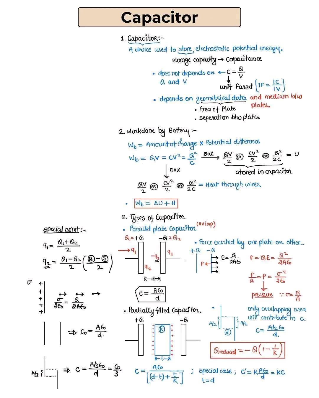
- 전하 분포: 평행판 축전기에서 극판의 전하는 크기가 같고 부호가 반대입니다. 극판에 Q₁과 Q₂의 전하가 있다면, 각 극판의 전하는 q₁ = (Q₁ + Q₂)/2 와 q₂ = (Q₁ - Q₂)/2 로 주어집니다.
- 평행판 축전기: 평행판 축전기의 축전 용량(C)은 다음과 같이 주어집니다: C = Aε₀/d , 여기서 A는 극판의 면적, ε₀는 진공의 유전율, d는 극판 사이의 거리입니다. 유전체(k)가 있는 경우 C = kAε₀/d 로 표현됩니다.
- 한 극판이 다른 극판에 미치는 힘: 극판 사이의 힘은 F = QE = Q²/2Aε₀ = σ²/2ε₀ 로 주어지며, 여기서 σ는 면전하밀도입니다. 이 힘은 압력과도 관련이 있습니다: P = F/A = σ²/2ε₀ .
- 부분적으로 채워진 축전기: 유전체로 부분적으로 채워진 축전기의 축전 용량은 다음과 같이 주어집니다: C = Aε₀/(d-t + t/k) , 여기서 t는 유전체의 두께이고, k는 유전율입니다.
4. 추가 설명:
이 필기에는 전하 분포와 부분적으로 채워진 축전기의 구조를 보여주는 그림이 포함되어 개념을 더 명확하게 설명합니다. 방정식과 그림은 축전기의 동작과 특성에 대한 포괄적인 개요를 제공합니다.
About the capacitor
It's about capacitors. A summary of the main concepts is as follows:
1. Definition of capacitor:
- A capacitor is a device that stores electrostatic potential energy.
- The storage capacity (C) represents the storage capacity, and the unit is **parrot(F)**.
- The capacitance of the capacitor is independent of the amount of charge (Q) and voltage (V) of the capacitor.
- Capacitance depends on the geometric elements (area of the plate, distance between the plates) and the medium between the plates.
2. Work by battery:
- What the battery does to charge the capacitor (Wb) is expressed as follows: Wb = QV = CV2/2 = Q2/2C
- Half of this energy is stored as electrostatic potential energy (U) in the capacitor, and the other half is dissipated as heat through the wire.
- Wb = ΔU + H where ΔU is the amount of change in potential energy, and H is the heat generated.
3. Special points and types of capacitors:
- Charge distribution: In parallel plate capacitors, the charge of the electrode plate is the same size and the sign is opposite. If the electrode plate has charges of Q1 and Q2, the charge of each electrode plate is given as q1 = (Q1 + Q2)/2 and q2 = (Q1 − Q2)/2.
- Parallel plate capacitor: The capacitor capacity (C) of the parallel plate capacitor is given as follows: C = Aε0/d, where A is the area of the plate, ε0 is the dielectric constant of the vacuum, and d is the distance between the plate plates. If there is a genome (k), it is expressed as C = kAε0/d.
- The force of one plate on the other: The force between the plates is given by F = QE = Q2/2Aε0 = σ2/2ε0, where σ is the surface charge density. This force is also related to pressure: P = F/A = σ2/2ε0 .
- Partially filled capacitor: The capacitor capacity of the capacitor partially filled with dielectric is given as follows: C = Aε0/(d-t + t/k), where t is the thickness of the dielectric, and k is the dielectric constant.
4. Further explanation:
This writing includes a picture showing the charge distribution and the structure of a partially filled capacitor, which explains the concept more clearly. Equations and figures provide a comprehensive overview of the behavior and characteristics of capacitors.